To understand why the memory test code is the way it is, I'll explain how memory works. Dynamic memory works pretty much this way whether you're using a Spectrum from 1982 or a PC from 2007 - the difference really is just in magnitude! There are of course some specifics which are a consequence of the Spectrum's 1982 design, which I'll go into.
|
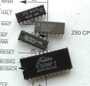
| Three types of 4116 and a 2Kbyte static RAM. All of these chips are 16384 bits, or 2Kbytes, and made in the early to mid 80s. The Toshiba chip has more pins since its data bus is 8 bits wide and addresses are accessed directly, rather than by row and column. This makes the Toshiba chip much easier to use but more expensive. The AMD chip is in a cerdip (ceramic) package for more punishing environments. |
The kind of memory that a Spectrum uses is dynamic memory. There are two major types of RAM you'll encounter - dynamic and static. They do the same job, but the underlying details are different. Static memory is made with transistors - 6 transistors per bit. It's very easy to use - generally, small SRAMs are directly addressed (meaning the CPU just presents an address on the bus plus either a read or write signal, and the SRAM outputs the contents of that byte, or loads the byte on the data bus). Dynamic RAM on the other hand essentially uses a capacitor as its memory storage unit. Generally, DRAM is accessed differently too - some extra logic is needed to turn the address on the CPU's address bus into a row and column address, since DRAM is generally accessed by row and column. In an ideal world, once the capacitor has a charge, it will never lose it. But in the real world, capacitors leak. Dynamic RAM therefore will lose its contents if the individual memory cells are not refreshed. The tradeoff for this extra complexity (the need to turn the address on the CPU's bus into a row/column address, and the need to refresh the memory) is that dynamic RAM is cheaper and has a greater memory density for a given die size.
The difference in price was quite significant in 1982. (These days, if you're making a small 8 bit machine with 48K of RAM, you'd use static RAM because the price difference for small amounts of memory is negligable). This is why Sinclair used DRAM instead of SRAM for the Spectrum.
The 48K Spectrum has two kinds of memory chips. The lower RAM, which contains things like the frame buffer and system variables area sits in the memory map between address 16384 and 32767. This is made up by 4116 memory chips. The upper 32K of RAM, from 32768 to 65535 is made up of 4164 chips. Most of the time, when a Spectrum won't initialize to the (c) 1982 message, it's because of a fault in lower memory.
A common assumption (which makes a BIG difference for a memory testing program) is that since the Spectrum is an 8 bit machine, the RAM chips hold the data in 8 bit wide chunks. This is a trap for the unwary - it's not true at all. All the memory on a 48K Spectrum is only one bit wide! If you look at the Spectrum's motherboard, you'll see there are eight 4116 and eight 4164 chips. If you then go and look at the schematic diagram, you'll see each 4116 and 4164 is connected to a single line on the data bus - so when the CPU reads or writes a byte of RAM, it selects all eight chips, and each chip yields one bit each of the byte that's being read. This means if you want to do something like an inversion memory test (where you store the pattern 101010101...) then doing the equivalent of POKE 16384, BIN 10101010 isn't going to be all that effective - since in the physical RAM chips, each chip will hold contiguous 1s or contiguous 0s. You actually need to POKE 16384, BIN 11111111 and then POKE 16385, BIN 00000000 (and so on) to perform an inversion test on a 48K Spectrum's memory.
The Spectrum 128K is a different beast; some models have 4 bit wide chips (so two chips are selected at once to yield all 8 bits for a given memory address). This means the memory tester for a 128K machine needs to be a bit different to take this into account.
We all learned that in a computer, you can only have 1 or 0, often thought of as 'on' and 'off'. At the hardware level this isn't quite true. There are actually THREE states, not two, and 0 does not mean 'off'. In the hardware, 1 is physically represented by a 5 volt signal. 0 is represented by a 0 volt signal. The third state (often referred to as an output being "tristated", or in "high impedance mode") is actually off. Logic 1 effectively means the output stage of the RAM chip is using a transistor to connect the +5v line to the chip's data output pin. Logic 0 means that the output stage is using another transistor to connect the 0v line to the chip's output. The high impedance state means that neither the 5v or 0v line is connected to the output - so the output is "floating". It's genuinely off. Thinking of it in lightswitch terms, a lightswitch's state is logic 1 or high impedance state - a light switch doesn't have a logic 0 state.
Why three states? This is to allow the bus to work. In a Spectrum, you have both the lower 16K and upper 32K RAM all connected to the same data bus. When an address on the lower 16K is selected for reading, the outputs of the 4116 chips will all be outputting logic 1s and 0s. If the 4164 upper memory wasn't in high impedance state, it would effectively cause a short circuit on the bus, and the signal from the 4116 RAM wouldn't ever get to the CPU. So while the 4164s are deselected, their outputs are truly "off", neither logic 1 or 0, so that the output from the 4116 RAM can get to the CPU.
So this leads us to the first class of failure - a failure that will prevent the diagnostics board from working at all - a RAM chip (or anything else that sits on the data or address bus for that matter, including solder bridges from splatter during chip desoldering operations!) that has failed in such a way that its output never goes into high impedance state. If this has happened, even when all the RAM is deselected, and the ROM is selected, the faulty RAM chip will be blocking a line on the data bus, so correct instructions from ROM will never make it to the CPU. Fortunately, this kind of failure is very rare. You may be able to detect it with a multimeter if the output is stuck on with logic 1. If it's stuck on logic 0 you'll need an oscilloscope to find out which bit of the data or address bus is being fouled (since the output stage of a RAM chip doesn't have zero resistance, what you're likely to see is a waveform that only reaches 2 volts - or some other intermediate voltage - when a chip tries to put a logic 1 on that particular part of the bus).
On the other hand, if the chip has failed such that it never leaves the high impedance state, the output will always appear to be set to logic 1 to the CPU. If a memory chip has failed in such a way that its output stays in high impedance state, the diagnostics board will identify the faulty chip with the first memory test.
Sometimes, you may get a bad bit - one that remains stuck on 0 or 1 while the rest of the chip functions fine. The first test that the testing board runs will detect these, because this just tries to set and reset each bit in turn, checking that the bit got set and reset. This kind of failure in lower RAM will likely stop the Spectrum from initializing. It's quite common that it'll affect the entire faulty chip - whichever memory address on the chip you read, you'll get the same bad value out. When the memory tester clears the screen at the end of all the tests, if the chip has failed stuck to logic 1, this is very visible as a set of vertical stripes running down the screen.
A more subtle failure which will not be detected by the Spectrum's power on memory check (but may still hang the machine or cause it to boot loop when the memory is used for real, and the stack or system variables get corrupted) is where setting one memory cell causes another memory cell to get set, or perhaps the wrong memory location altogether. A failure of either the row or column selection logic inside the memory chip can cause this to happen (such that whatever address you select, only one actual memory cell ever gets selected). Obviously, this won't be detected by setting all of memory to a uniform value and reading it back. The memory tester routine writes 'inversions' to test for this - first, the whole of the memory bank is set to a particular value, and then alternating locations are set to that value's complement - and then the memory is read back to ensure it contains alternating values. A number of inversion patterns are tested: for example, setting all of a memory bank to contain 0x00, and then putting 0xFF in alternate memory locations (remember, memory is one bit wide, so alternate memory addresses, not bits within a byte, will represent the pattern 101010101... in the actual chip). Then doing the opposite - setting the entire bank to 0xFF, and writing 0x00 in alternate locations. This is to catch a number of classes of problems - problems where setting a bit to 1 causes an adjacent bit to flip to 1, and cases where resetting a bit will cause another bit to reset.
The inversion test will catch many problems that the Spectrum's ROM won't catch. It will also catch problems that the first memory test (the simple bit set and reset test) won't catch.
However, there are yet more subtle memory faults where adjacent locations can be affected. An example may be that part of the column select logic in the chip has gone faulty, such that most of the columns get selected correctly, but one of the column address bits is stuck on. This means that if you just check adjacent bits to see if they get flipped, you may never catch the problem. Indeed, with just a simple 101010101... pattern, the problem may be impossible to find. The two addresses being affected by the fault might be in different halves of the chip. So a third test is run - a pseudo random number generator is used to fill the memory bank, and then the bank is read back, comparing against a second run of the random number generator (which given the same seed value as for the set operation, will provide exactly the same sequence of numbers for the read operation, and can be used to compare against the contents of RAM).
While there are a raft of internal faults with the chip that might have caused it to die, such as bad memory cells, faulty row/column select logic or faulty data input/output circuitry - there are also external problems that can beset a Spectrum's memory. This is mostly concerned with the lower 16K.
The upper 32K is quite simple - this memory uses a single power supply which consists of ground and 5 volts (GND and Vcc respectively). The power brick (nominally 9 volts) for the computer is fed through a 7805 voltage regulator, which gives a very stable 5 volt output. The 7805 is a robust device, complete with short circuit protection and overheating protection. They are quite difficult to kill. If the Spectrum does anything at all when powered up, it's likely the regulator is working to spec (but it's a good idea to check it with a multimeter anyway).
The lower 16K, consisting of 4116 memory is another matter entirely. This chip has not the usual two supply rails (Vcc and GND) - but no less than four supply rails! It requires +5 volts, -5 volts, +12 volts and GND! These extra voltages - the -5v and +12v, are generated by a small switch mode power supply on the Spectrum's motherboard. This is driven directly by the Spectrum's 9v power pack. The kind of hissing noise you can hear from a healthy 48K Spectrum's motherboard does not come from the machine's speaker as is generally assumed, but is generated by the inductor on this power supply - and you can hear it change note slightly as the Spectrum draws differing amounts of current. The oscillator circuit must respond to the change in current draw, and so as the Spectrum's current draw changes, you can hear the sound that comes from the coil also changing.
There is a transistor in that power supply circuit which often lets the magic smoke escape - and if that happens - the 5 volts will still be supplied by the 7805 regulator, but the -5v and +12v supplies will not be getting generated - and the 4116 chips won't work at all (and indeed, they may also be damaged - the data sheet for the TMS4116 states that the -5v supply must be supplied first and removed last, or the chip may be destroyed. If only the 5v power is being supplied and the -5v/+12v is not present at all - the bad condition is happening). Incidentally, this is one reason why accidents with the edge connector tends to kill a Spectrum - if the +12v/-12v/-5v signals on the edge connector get shorted, it can kill this power supply, which in turn kills the 4116 memory, or at the very least, prevents it from functioning until the power supply is fixed.
This is why I've made the first step in the instructions to check the voltages to the 4116 memory - because this is the "low hanging fruit" of Spectrum fault finding.
Occasionally, "dry joints" and broken tracks prevent a Spectrum from working, particularly if it's undergone prior repair work and has had some hand soldering done to it. If the diagnostics board identifies a bad chip and you replace it and it still doesn't work, it's worth checking the continuity of the track. You'll need to refer to the Spectrum schematic for your model to know which pins to test continuity between (you'll need to check the data bus to the ULA and CPU, and the address bus to the row/column demultiplexing logic).
As noted right at the start of this article, the memory needs some supporting logic to turn an address from the CPU into row and column addresses for the memory. If continuity is good on the board, this is the next place to look. It's quite rare that LSTTL chips fail, but it can happen. The ULA is also involved with the 4116 chips, and since the ULA is socketed, if you have a spare that is known good, it's worth doing since this won't require any soldering and is fast to do. LSTTL chips are no longer made, however, Bowood Electronics still sells them. You can also substitute 74LS family ICs with 74HCT CMOS chips, which are direct CMOS replacements for the 74LS series. If there's a problem with the logic, the diagnostics board will most probably show this as ALL eight chips of that bank having failed - however, the chip select logic can have partial failures too.