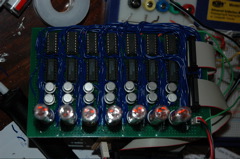
The completed board - 7 IN-16 nixies, 7 K155ID1 driver ICs, 7 4050 CMOS buffer ICs, 14 transistors, 14 1K resistors, 7 33K resistors. Two 20-pin connectors and a 2 pin connector. That's a lot of soldering and track cutting...
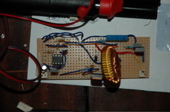
The switch mode power supply - soldered up and WORKING!
Final prototyping under way
The registers now on the logic board.
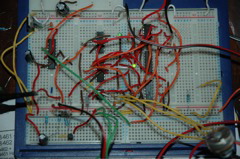
...with the decoder breadboarded since I had some tests and improvements to make over the original prototype
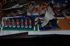
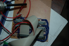
The decoder now soldered onto the logic board, the time display being sent over RS232
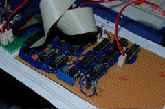
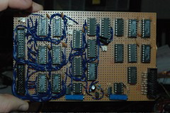
A shot of the logic board - decoder and registers all connected and working. Note the liberal use of ceramic disc capacitors!
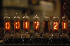
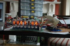
Yes, it's bloody late, but it's WORKING! (Yes, tube 5 is supposed to be blanked before you ask). Naturally, this is NTP synchronized.
The completed logic board.